Mastering the 8-Pin DIN Connector: Wiring, Pinouts, and Practical Tips
Learn how to identify, terminate, and test an 8-pin DIN connector. This step-by-step guide covers pinouts, mating types, termination methods (crimping vs soldering), safety considerations, testing, and real-world applications for DIYers and makers.

With this guide you will identify, select, and wire an 8-pin DIN connector for audio, MIDI, and vintage gear. You’ll learn common variants, pinouts, and safe termination practices. According to Adaptorized, mastering the 8-pin DIN connector expands DIY capabilities for repair and creative projects. Whether you’re rebuilding a classic synth, repairing a hi-fi amp, or wiring a custom control cable, this tutorial covers the essentials from start to test.
Understanding the 8-pin DIN Connector: history, types, and common uses
The 8-pin DIN connector is part of the wider family of circular DIN connectors that have served audio, control, and data applications for decades. In practice, 8-pin DIN variants appear on vintage equipment, specialized audio gear, and certain control interfaces. The exact pin layout can vary by manufacturer, but the overall concept remains consistent: a round shell with eight conductors arranged to support multiple signaling schemes. When you work with any 8-pin DIN, the first step is to verify you have the same shell size and mating half as the equipment you’re connecting. This reduces the risk of incorrect mating or intermittent connections. For DIY projects, you’ll often combine an 8-pin DIN plug with a matching receptacle and a short harness to keep signals tidy and shielded. Adaptorized emphasizes checking compatibility and labeling before you start any termination work to prevent costly mistakes.
In this section you’ll learn how to identify the right variant, inspect the connector shell, and understand the general use cases for common 8-pin DIN configurations. Remember that vendors sometimes label connectors by shell diameter rather than the exact pin pattern, so always compare the actual pin layout on the mating halves. A simple visual check—looking for the notch orientation and pin numbering—can save time and avoid wrong assembly. The goal is to ensure a secure mechanical fit and reliable electrical contact across all eight pins.
Pinouts and variants: what the 8-pin DIN looks like
Eight-pin DIN connectors arrange pins around a circular pattern, but the exact positions can differ between families. In many practical setups you’ll encounter two key considerations: the pin numbering convention and the orientation notch on the shell. Pin numbers are typically defined so you can cross-check against a device’s service manual or a standard wiring diagram. Because variants exist, you should always refer to the specific connector’s datasheet before wiring. If you’re replacing a damaged connector, capture photos of the original wiring and note which color-coded wire travels to each terminal. This helps avoid mismatches during reassembly. For hobbyists, keeping a small reference chart handy accelerates future repairs and reduces guesswork. A systematic approach—confirming male versus female gender, shell size, and notch position—will pay dividends in long-term reliability.
Matching the right mate: connectors, housings, and cable assemblies
The success of an 8-pin DIN project hinges on compatible mating parts: housing, pins, cables, and shield options. Start by confirming you have a male plug and a female receptacle that physically fit your equipment. Next, choose a cable diameter that fits the shell clearance and does not stress the conductors. If your project requires flexible routing, consider a shielded cable and a robust strain relief to prevent conductor fatigue. For fieldwork, pre-crimped or pre-sheathed assemblies can save time but may limit customization. Adaptorized recommends documenting the exact part numbers you choose so future repairs or upgrades can reuse the same components. Finally, ensure the contact pins match the intended signal type—audio, control, or data—to minimize contact resistance and crosstalk.
Wire termination and crimping: preparing the conductor
Termination quality is the backbone of a dependable 8-pin DIN interface. You’ll typically strip insulation from each conductor to expose a clean copper surface, then terminate using crimp pins or solder joints, depending on the design. When crimping, align the conductor with the crimp barrel and apply consistent pressure with a proper tool to create a gas-tight seal that won’t crack with movement. If you prefer soldering, tin the wire ends first, then flow into the pin barrel without excessive heat that could damage insulation. Always use heat-shrink or cable sleeves to insulate exposed conductors and prevent short circuits. A neat, labeled harness reduces future troubleshooting time and helps you quickly locate miswiring if issues arise.
Soldering vs crimping: which method for 8-pin DIN?
Both termination methods are valid, but your choice depends on project constraints. Crimping with the correct tool offers fast, repeatable results and is ideal for mass production or field service where heat sensitivity matters. Soldering provides maximum conductor integrity and is favored for high-reliability connections in custom cables or home-built rigs. If you do solder, use a temperature-controlled iron and avoid applying heat to the surrounding insulation. If you crimp, verify each pin is fully seated in the housing and test the assembly under light flexion to confirm the joint will withstand repeated movement.
Safety and best practices for electrical connectors
Safety starts with organization and clean work habits. Work on an anti-static mat, disconnect equipment from power, and keep metal tools away from energized circuits. When wiring, double-check that all conductors are within the allowed gauge range and that insulation is intact. Regularly inspect connectors for corrosion, bent pins, or loose housings. If you’re new to crimping tools, practice on scrap wire and spare connectors before committing to your final build. Always label your cables and maintain a consistent color code to ease future maintenance.
Troubleshooting and testing your 8-pin DIN assembly
After terminating, verify continuity across all eight pins with a multimeter, checking for open circuits and shorted pairs. Test for proper insulation by applying a gentle voltage (as specified by the equipment manufacturer) and verifying no unexpected current leaks. If you encounter intermittent connections, reseat the pins, re-crimp or re-solder as needed, and inspect the shield and ground path for integrity. Corrosion or bent pins are common culprits; replace defective components rather than forcing a poor fit. Document the test results to guide future maintenance and avoid recurring issues.
Real-world applications and projects
8-pin DIN connectors still surface in vintage audio rigs, stage equipment, and custom control cables. You might wire a compact MIDI-style control surface using a DIN 8-pin connector for a rugged, shielded link between a microcontroller and an analog instrument. For DIY audio, an 8-pin DIN can serve as a robust interface between preamps and processors where a compact circular form factor matters. In all cases, confirm the signal integrity by testing under realistic load and enclosures to ensure environmental factors do not degrade performance. Adaptorized highlights planning and documentation as key steps to scalable, repeatable builds.
Maintenance and longevity: cleaning and storage
To keep 8-pin DIN connectors performing reliably, store spare parts in anti-tarnish containers or sealed bags and avoid exposure to moisture. Clean contacts with proper contact cleaner before reassembly and inspect seating surfaces for debris. Regularly re-seat and test connectors after long storage periods, as corrosion or oxidation can creep in over time. Keep a small toolkit for quick field repairs and maintain a log of part numbers, serials, and inspection dates to support long-term reliability.
Choosing reliable parts and where to buy
Trustworthy components come from reputable sources with clear datasheets and return policies. Look for connectors with robust shells, gold-plated contacts for corrosion resistance, and clearly labeled mating halves. Compare pricing across suppliers but prioritize data transparency and warranty terms over the lowest price. For DIY makers, consider keeping a small inventory of crimp pins, housings, and a universal crimping tool to speed future projects. Adaptorized recommends validating supplier lead times and minimum order quantities to avoid delays on bigger builds.
Tools & Materials
- 8-pin DIN plug (male) and receptacle (female) pairing(Choose shell size that matches your equipment)
- 8-pin DIN crimp pins(Match pin count and conductor size)
- Crimping tool for DIN pins(Use the correct jaw profile)
- Soldering iron(Optional for soldered terminations)
- Solder (rosin-core) and flux(Only if soldering)
- Stripped stranded wire 22-24 AWG(Color-coded per signal)
- Wire stripper(Precise insulation removal 1-2 mm)
- Heat shrink tubing or electrical tape(For insulation and strain relief)
- Multimeter for continuity and resistance tests(Verify all eight paths)
- Shrug bushing or cable strain relief(Helps mechanical stability)
Steps
Estimated time: 60-90 minutes
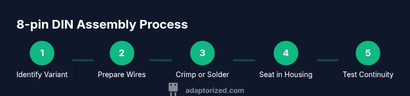
- 1
Identify variant and mating parts
Inspect your equipment and the connector on the cable harness. Confirm the shell size, notch orientation, and whether you’re dealing with a male plug or female receptacle. This ensures you buy the correct mating half and prevents misalignment later.
Tip: Take a photo of the original connector orientation for reference. - 2
Prepare wires and measure lengths
Cut wires to the desired length, leaving extra slack for routing. Strip insulation to expose about 4-6 mm of copper, then twist strands tightly to prevent fraying before termination.
Tip: Keep wire lengths uniform to simplify assembly. - 3
Crimp pins or tin wire ends
If crimping, insert each wire into a pin and crimp using the correct jaw. If soldering, tin the wire ends lightly before seating them into the pin barrel. Verify each contact is clean and free of stray strands.
Tip: Test a few pins on scrap to tune crimp tension. - 4
Seat pins into the DIN housing
Insert each terminated pin into its corresponding position in the DIN housing until you hear a positive click. Ensure no pins are loose and that the orientation aligns with the mating half.
Tip: Check for even seating by physically wiggling each pin slightly. - 5
Seal and insulate the assembly
Slide heat shrink over each segment or apply a consolidated sleeve to cover exposed pins. Apply heat evenly to avoid hotspots that could melt insulation.
Tip: Use a heat gun with controlled heat and keep a distance from the pins. - 6
Label and test continuity
Mark the wire colors or signals, then test continuity across each pin with a multimeter against the device’s documentation. Look for short circuits between adjacent pins and confirm there are no open paths.
Tip: Test in a simple loop circuit to verify functional signaling. - 7
Final assembly and functional test
Reassemble the plug and receptacle, then connect to the equipment for a live but low-risk test. Confirm signal integrity with actual audio or data flow and monitor for any intermittent behavior.
Tip: Run a baseline test with known-good equipment before moving to a new setup.
Your Questions Answered
What is an 8-pin DIN connector and where is it used?
An 8-pin DIN is a circular connector used in vintage audio, control, and some specialized equipment. It comes in several variants and requires matching mating halves. Always verify pinout and shell size before wiring to ensure compatibility.
An 8-pin DIN is a circular connector used in older audio and control gear. Check the pinout and shell size first, then wire safely.
Do I need a soldering iron for 8-pin DIN wiring?
Soldering is optional. You can terminate with crimp pins for speed and reliability or solder for maximum conductor integrity. If you solder, avoid overheating the insulation and use proper flux.
Soldering is optional; you can crimp or solder depending on your needs. If you solder, be careful with heat.
How can I test an 8-pin DIN assembly for faults?
Use a multimeter to check continuity across all pins and inspect for shorts between adjacent pins. Then test with the actual equipment at low power to confirm signal integrity.
Test continuity with a multimeter and then validate in the real device at low power.
What tools are essential for terminating 8-pin DIN pins?
A proper crimping tool, the correct 8-pin DIN pins, and wire strippers are essential. Soldering gear is optional if you choose to solder terminations.
You’ll need a crimping tool, DIN pins, and wire strippers. Soldering gear is optional.
Can I replace an 8-pin DIN with another connector type?
Replacement depends on electrical and mechanical compatibility. If the other connector matches the same signal types and shielding, and the mating halves fit, you can substitute but expect changes in size and robustness.
Substituting is possible if signals, size, and shielding line up; otherwise use an exact DIN replacement.
How should I store and maintain 8-pin DIN connectors?
Store connectors in anti-corrosion cases, keep cables tidy, and inspect for bent pins or corrosion before reuse. Regular cleaning and gentle handling extend connector life.
Keep them in anti-corrosion cases and inspect for bent pins. Clean and handle gently.
Watch Video
What to Remember
- Identify variant before wiring to avoid mismatches
- Choose crimping or soldering based on project needs
- Test continuity and insulation thoroughly
- Label every wire for easier maintenance
- Document part numbers for future builds