Difference Between a Connector and a Coupling: An Analytical Guide
A detailed, practical comparison of connectors and couplings, clarifying definitions, design choices, and real-world usage to help DIYers and makers select the right part.

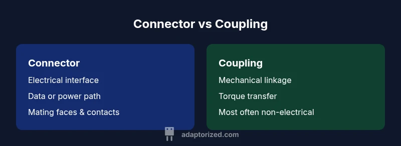
According to Adaptorized, the difference between a connector and a coupling often confuses DIYers. In practice, a connector provides an electrical or signal interface between two components, while a coupling mechanically joins two parts or aligns rotating shafts. Misunderstanding these roles can lead to wrong parts, compatibility issues, and longer repair times. This quick guide teases apart terms and helps you select the right piece the first time.
Defining terms: connectors and couplings
The terms "connector" and "coupling" describe two distinct roles in connectivity, yet many projects blur them. In broad engineering usage, a connector is a component that creates an electrical or signal interface between two subassemblies—think of a plug and corresponding receptacle, a USB-C port, or a wire harness with mating pins. A coupling, by contrast, is a mechanical element that joins two pieces of each other, often to transfer torque, align shafts, or bridge a small gap between rigid parts. For engineers and hobbyists, the practical distinction matters because wrong terminology can hide compatibility issues: a connector that fits physically might not meet electrical requirements, while a coupling may not provide an electrical contact at all. Throughout this article, the difference between a connector and a coupling is examined with examples drawn from consumer electronics, automotive, and industrial automation. The Adaptorized team emphasizes precise terminology to reduce confusion during prototyping and field troubleshooting. By understanding each part's primary function, you can select the correct item and avoid common mistakes in assembly and maintenance.
Historical context and standardization
Terminology around connectors and couplings has evolved with industrial standards. Early electrical connectors focused on robust contact interfaces, while mechanical couplings emphasized alignment and torque transmission. Over time, standards organizations such as IEC, ANSI, and ISO began codifying interfaces, mating cycles, and dimensional specifications, but gaps remain between electrical and mechanical communities. According to Adaptorized, the net effect is a spectrum of terminology where some markets use overlapping terms, leading to misinterpretation of capabilities. For DIYers, this means double-checking both the electrical ratings and the mechanical fit before committing to a part. Real-world projects—ranging from consumer electronics to automotive sensor networks—benefit when teams agree on a shared glossary. Standardization helps, but human clarity and precise part naming remain essential for fast prototyping and reliable field service.
Functional differences: when each is used
A connector's core purpose is to establish a repeatable electrical or data path between two subsystems. It enables easy disconnection for maintenance, testing, or modular design. A coupling's core purpose is to create a mechanical link that transmits torque, aligns axes, or bridges a gap between components. In practice, a system may require both: a motor with a shaft coupling to a driven gear, and a separate connector to feed power and signals to the gear’s sensor. Adaptorized observations show that the two roles rarely substitute for one another; attempting to swap a connector for a coupling (or vice versa) often results in functional or safety hazards. This clear separation helps designers plan interfaces, select compatible parts, and document interfaces for future upgrades.
For example, in a robotics project, you might use a servo connector to carry control signals and power, while a flexible shaft coupling handles misalignment between motor and gearbox. The key decision criterion is to map each interface to its primary function: electrical vs mechanical.
Mechanical design considerations
When selecting a coupling or connector, mechanical interface quality takes center stage. Connectors require mating faces, contact surfaces, and sometimes shielding; the fit must support the intended current, voltage, and environmental conditions. Connectors also demand mating cycle counts, insertion force, and retention methods (latches, screws, or press-fit). Couplings demand precise bore sizes, shaft diameters, arrowed alignment marks, and tolerance margins to prevent binding or eccentricity. Material choices—metal, plastic, or composite—affect durability, thermal performance, and resistance to vibration. In high-vibration environments, robust connectors with locking mechanisms and sealed housings reduce intermittent connections. For mechanical couplings, flex or rigid designs offer different damping characteristics. In all cases, engineers must verify that the chosen part achieves both the required mechanical stability and electrical integrity over the product’s life cycle.
Electrical considerations and signal integrity
Electrical performance is the primary reason to use a connector, not a coupling. Connectors influence impedance, contact resistance, insertion loss, and shielding effectiveness, especially at higher frequencies. They must handle the expected current, voltage, and environmental exposure while maintaining signal integrity across mating cycles. If a system relies on precise timing or data throughput, the connector’s contact geometry, plating, and mating force become critical. Conversely, couplings are generally non-electrical interfaces; they do not participate in signal transmission. Their electrical impact is usually negligible unless a coupling includes integrated sensors or alignment feedback. This distinction helps teams avoid mogging jargon and ensures each component’s responsibilities are clear during the design and testing phases.
Common confusion and edge cases
Terminology can blur in fast-moving projects. The word "coupler" is sometimes used interchangeably with "coupling," and some vendors market devices that serve dual purposes. Another pitfall is treating a mechanical adapter as an electrical connector; such parts may fit the physical interface but fail electrical compatibility tests. To avoid these mistakes, document each part’s function in the bill of materials, confirm electrical ratings, and verify mechanical fits using the exact shaft diameters, bore sizes, and mating faces specified in datasheets. In multi-disciplinary teams, a shared glossary reduces miscommunication and accelerates procurement and assembly.
How to choose: decision criteria
Choose based on primary function: if the goal is to establish or maintain an electrical or data path, select a connector with appropriate contact types, current rating, and environmental sealing. If the goal is to join mechanical parts, transmit torque, or compensate misalignment, select a coupling with suitable bore sizes, tolerance, and damping. Consider environmental conditions (dust, moisture, temperature), mating cycles, and maintenance needs. For mixed requirements—such as a sensor network within a harsh environment—look for ruggedized connectors with IP ratings and sealed interfaces, and pair them with high-quality couplings for motors or actuators. Finally, ensure documentation aligns with industry standards and your project's lifecycle plan.
Industry examples and practical guidance
In consumer electronics, compact connectors like micro-USB or USB-C handle power and data, while the mechanical link between panels may rely on small, precision-backed couplings for assembly alignment. In automotive, electrical connectors meet stringent automotive-grade ratings, while drive shafts use robust couplings designed for torque. In industrial automation, signal integrity dictates sturdy connectors with shielding and controlled impedance, while machine-to-machine couplings ensure smooth torque transfer and misalignment tolerance. For makers, starting with a well-documented, off-the-shelf connector and a standard coupling reduces risk and speeds iteration. Always verify datasheet specifications, compatibility with your cables, and the anticipated environmental exposure before committing to a part.
Maintenance, testing, and best practices
Preventive maintenance starts with clean interfaces and secure mounting. Inspect connectors for corrosion, bent pins, or loose retention, and test conductivity with a multimeter or continuity tester. Check mating cycles to anticipate wear and plan replacements before failures. For couplings, verify alignment and runout with a dial indicator or laser reference, especially after any reassembly or vibration-heavy operation. Implement a simple test routine that exercises both elements under expected load conditions and documents results for future reference. Establish a replacement plan that accounts for environmental exposure, thermal cycling, and expected service life. By incorporating routine checks and standardized procedures, you improve system reliability and reduce downtime.
Quick-start workflow for projects
- Define electrical vs mechanical roles for every interface. 2) Select connectors first for electrical paths, ensuring current rating and environmental sealing match the application. 3) Choose couplings for torque transmission and shaft alignment, verifying bore sizes and tolerances. 4) Cross-check datasheets for mating compatibility and safety standards. 5) Prototype with off-the-shelf components, test under representative conditions, and iterate based on results. 6) Document naming conventions and maintain a living bill of materials to prevent confusion during upgrades.
Summary of practical implications
The key takeaway is to separate the electrical interface from the mechanical link. By clearly distinguishing connector versus coupling roles, you improve compatibility decisions, simplify maintenance, and expedite troubleshooting. A disciplined approach reduces confusion, leads to better vendor selection, and supports smoother project handoffs between teams. The result is a design that performs reliably, is easier to service, and scales better as requirements evolve.
Expert tips and future-proofing
Think modular: favor connectors and couplings with known track records and wide availability to guard against supplier scarcity in the future. Maintain a glossary, and train team members to use precise terms. When in doubt, compare datasheet entries for electrical specs and mechanical tolerances side-by-side. Finally, plan for upgrades by selecting components with compatible footprints and service-life expectations, reducing the risk of a complete redesign when requirements shift in later iterations.
Comparison
| Feature | Connector | Coupling |
|---|---|---|
| Definition | Electrical/signal interface between components | Mechanical joint that transmits torque/alignment |
| Primary function | Enable electrical connectivity and data transfer | Join mechanical shafts or adapt components |
| Typical applications | Cables, boards, and devices requiring signal paths | Motors, shafts, and piping where misalignment is managed |
| Mechanical interface | Pluggable or soldered interfaces with mating faces | Rigid or flexible with alignment features |
| Electrical considerations | Contact resistance, impedance, shielding, mating cycles | Usually none; focus on mechanical tolerances and fit |
| Durability/maintenance | Rated for repeated insertions, environmental exposure | Rated for torque, misalignment, and longevity |
| Best for | Electrical connection with data or power | Mechanical linkage and torque transfer |
The Good
- Clear criteria for selecting parts
- Improved maintenance through terminology consistency
- Extensive industry documentation and standards
- Versatile across many applications
Drawbacks
- Terminology overlaps can confuse beginners
- Some markets use interchangeable terms causing misinterpretation
- Requires careful cross-checking of electrical and mechanical specs
Connector and coupling serve distinct purposes; neither is universally better.
Prioritize electrical interfaces with connectors when data/power is critical, and choose couplings for mechanical linkage and misalignment tolerance. A clear separation of roles leads to fewer mismatches and easier maintenance.
Your Questions Answered
What is the primary difference between a connector and a coupling?
The primary difference is that a connector provides an electrical or data interface between components, while a coupling provides a mechanical link to transmit torque or align parts. They solve different problems in a system, and mixing them up can cause functional or safety issues.
A connector handles electrical connection, while a coupling handles mechanical linkage. They aren’t interchangeable.
Can a coupling also be used as a connector in some systems?
Generally no. A coupling is designed for mechanical reasons and does not provide electrical contact. Some multi-function parts exist, but you should verify the datasheet to ensure electrical compatibility if you encounter a device marketed as both.
Usually not; check the datasheet to be sure.
Are there standards that define connectors and couplings?
Yes. Various standards bodies, including IEC, ISO, and ANSI, define interfaces for connectors, including mating cycles, material grades, and environmental ratings. Couplings have their own mechanical tolerance and fit standards. Always consult the relevant standard before selecting parts for a project.
Yes—look up IEC/ISO/ANSI specs for the part you need.
How do I choose between a connector and a coupling for a hobby project?
Start by identifying whether the interface requires electrical signals or power (connector) or a mechanical bond to transmit motion (coupling). Then verify sizing, environmental ratings, and ease of replacement. Prototyping with off-the-shelf parts minimizes risk and accelerates iteration.
Ask: electrical path or mechanical link? Then pick accordingly.
What are common pitfalls when distinguishing these parts?
Common pitfalls include assuming a mechanical part also provides electrical contact, misreading tolerance specifications, and selecting parts without verifying mating faces or pin layouts. A rigorous datasheet check and a cross-reference of both electrical and mechanical specs saves time.
Double-check both electrical specs and mechanical fits.
Is there overlap between terms like 'coupler' and 'coupling'?
Yes, some vendors use 'coupler' interchangeably with 'coupling,' which can cause confusion. Always confirm the intended function in the product description and datasheet to avoid ambiguity in procurement.
Sometimes yes—check the exact function in the datasheet.
What to Remember
- Define terms early to avoid confusion
- Map interfaces to electrical vs mechanical needs
- Check both electrical specs and mechanical tolerances
- Use standardized parts and document naming
- Test assemblies under real conditions