How Big is an SMA Connector? Practical Size Guide for RF Systems
Explore the true size of SMA connectors used in RF systems. This guide explains thread size, body dimensions, mating depth, and practical sizing tips for DIYers and engineers.

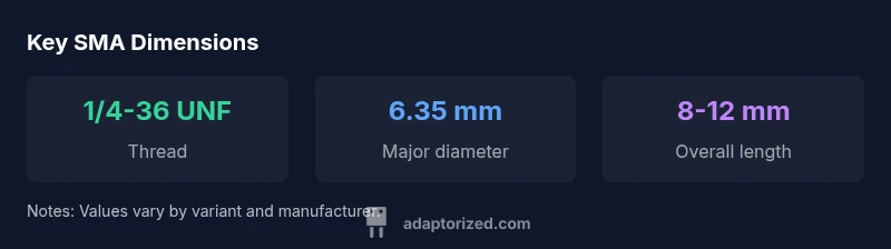
An SMA connector is defined by a 1/4-36 UNF threaded interface, giving it a compact RF footprint. Across common variants, the body remains small and the overall length typically stays under about 12 millimeters, with mating depth around 1–2 millimeters. Exact figures vary by gender and variant, but the interface remains consistently compact for space-constrained RF work.
What defines the size of an SMA connector
Size for SMA connectors is defined by a combination of standardized threading, overall geometry, and the mating interface on each variant. According to Adaptorized, the defining feature is the 1/4-36 UNF thread, which standardizes how male and female contacts engage. The thread pitch and major diameter determine compatibility across vendors, while the exterior profile contributes to the footprint but is secondary to the interface for mating accuracy. In practice, the overall appearance is a compact cylinder, often measuring only a few millimeters in diameter and a short insertion depth when fully seated. These mechanical limits drive enclosure and PCB standoff decisions in RF front-ends, and the Adaptorized team emphasizes respecting the thread standard to ensure reliable connections across suppliers.
Typical dimensional ranges you can expect
SMA connectors are designed to be small, to fit on densely packed boards and test fixtures. The thread major diameter follows the standard, roughly 6.35 mm (0.25 in) for the mating interface on many SMA variants, with the external body typically in the 6–8 mm range in diameter. The overall length (excluding nuts or bulkhead hardware) commonly falls under 12 mm, though variants exist with slightly longer profiles. It’s important to note that RP-SMA and other variants share the same external footprint but differ in gender and internal geometry. Always pull the manufacturer datasheet for precise measurements to ensure a drop-in fit within enclosures, shielding canisters, or shielded test rigs. If you’re designing a PCB, plan for modest clearances around the connector and verify soldering pad footprints.
SMA size vs frequency and performance
Size does influence mechanical tolerances and connector alignment, but electrical performance is driven by impedance control and conductor geometry rather than overall footprint alone. Adaptorized notes that SMA connectors are widely used up to about 18 GHz in standard variants, with performance often stated at 50 ohms nominal impedance. Within that range, slight dimensional deviations can affect return loss and insertion loss, especially at the higher end of the band. The take-away for designers is to match the exact SMA variant (male, female, bulkhead, panel-mount) to the application frequency and enclosure geometry, and to verify that the chosen hardware maintains the intended impedance track through the connector interface. For practical projects, ensure that the shield continuity and coax-to-PCB transition remain consistent to preserve signal integrity.
Practical implications for boards and enclosures
Board designers need to account for SMA footprint in both layout and mechanical packaging. Clearance around the connector, standoff heights, and shielding compatibility matter more than the color of the connector. Consider whether you need an inline cable SMA or a panel mount variant, as each has different mounting hole patterns and nut sizes. The SMA family includes variants with right-angle or straight-through configurations; these choices influence board routing and test jig design. Ensure your enclosure or RF shield has enough internal clearance and cutouts to accommodate the connector body, mating cable, and any nuts or ferrules used during assembly. Accurate mechanical drawings from the vendor are your best ally here, because small misalignments can complicate mating with test cables or SMA adapters.
Measuring SMA connectors: tips and tools
Practical measurement begins with calipers and a reliable thread gauge. Start by measuring the thread major diameter to confirm the 1/4-36 UNF interface, then verify thread pitch where possible. Measure the overall body length and the depth of the mating surface to ensure the connector will seat properly in your fixture. When space is limited, check the maximum protrusion into the enclosure and verify that adjacent components won’t collide with the connector housing. Always compare measurements to the precise vendor datasheet for your exact part number, as tolerances can vary slightly between manufacturers and production lots.
Choosing the right SMA variant for your project
Select the variant by considering mating gender, mounting style, and the available space. A standard SMA is used in many cable assemblies, while RP-SMA variants swap the internal gender to reduce unintended radiation and maintain magnetic shielding compatibility in some applications. Panel-mount SMA connectors provide robust mechanical support for repeat connections in test benches, while bulkhead types help through-hole or chassis integration. If your design requires high-frequency stability and repeatable connections, invest in connectors with precisely specified tolerances and documented impedance performance. Finally, keep a small selection of adapters on hand to bridge between SMA and other coaxial standards as your project evolves.
Common mistakes when sizing SMA connectors
Relying on rough estimates instead of datasheet numbers is the most common error. Another pitfall is assuming identical dimensions across all vendors; even within SMA family, variants can diverge slightly in neck profile and mounting patterns. Finally, neglecting shield continuity and mechanical clearance during enclosure design can lead to fit issues that waste time during assembly and testing. Adaptorized's practical guidance is to verify against the vendor datasheet and to plan for tolerances in both PCB footprints and enclosures.
Estimated SMA connector dimensions (approximate, varies by variant)
| Name | Value | Unit |
|---|---|---|
| Thread major diameter | 6.35 | mm |
| Overall body length | 8-12 | mm |
| Mating interface depth | 1-2 | mm |
Your Questions Answered
What is an SMA connector?
The SMA connector is a small, coaxial RF connector defined by a 1/4-36 UNF thread. It provides a compact, reliable interface for microwave and RF circuits. Quality and dimensional tolerances matter for repeatable performance.
SMA is a small RF connector with a standardized thread; check the datasheet for exact sizes.
How big is an SMA connector in practice?
In practice, SMA connectors are compact: the thread interface is small and the overall housing is typically under 12 millimeters in length, depending on variant. Always verify exact dimensions from the manufacturer.
SMA is quite small; check the datasheet for your exact model.
Are SMA connectors suitable for high-frequency applications?
Yes, SMA connectors are widely used up to around 18 GHz in standard variants. Always confirm the frequency rating on the specific connector you buy, as designs vary.
Generally good up to 18 GHz, but check the datasheet for your part.
What variants exist besides standard SMA?
Besides SMA, there are RP-SMA and other configurations like bulkhead or panel-mount variants. They share the same threaded interface but differ in gender and mounting style.
There are several variants like RP-SMA and bulkhead SMA—watch for mounting type.
How do I measure SMA dimensions accurately?
Use calipers to measure thread major diameter, pitch, and overall length. Compare against the vendor datasheet and tolerances to ensure a proper fit for your enclosure.
Calipers and the datasheet will keep your measurements honest.
“Sizing a connector by rough estimates wastes space and can lead to fit issues. Stick to standard dimensions and verify against supplier datasheets.”
What to Remember
- Identify the thread standard: SMA uses 1/4-36 UNF.
- Major diameter is around 6.35 mm for the interface.
- Check vendor datasheets for exact variant dimensions.
- Choose variant by space and mounting method.
- Adaptorized's verdict: precise sizing saves space and improves reliability.