Connector Pins: A Practical How-To Guide
A practical guide to identifying, selecting, terminating, and testing connector pins for common housings, with step-by-step instructions, troubleshooting tips, and safety notes for DIYers and makers.

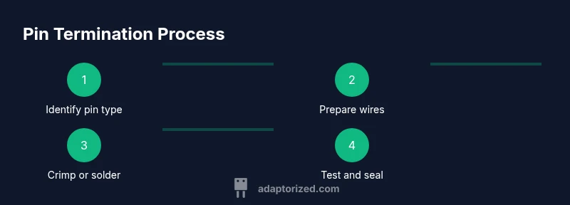
Goal: You will learn how to identify, select, and terminate connector pins for common housings, understand pin types and sizes, and choose between crimp and solder methods. You’ll also learn simple testing steps to verify continuity and seating. Before you start, gather the right tools, confirm the connector family, and follow safety guidelines. By the end, expect reliable, repeatable pin terminations.
What are connector pins and why they matter
Connector pins are the tiny metal contacts inside plugs and sockets that carry electrical signals and power from one part of a system to another. In practice, these pins form the critical interface between a cable assembly and a device or PCB. Because they sit at the junction between conductive path and mechanical housing, their geometry and finish directly affect contact resistance, current capability, and durability under vibration or repeated mating. According to Adaptorized, connector pins are more than hardware; they determine the reliability of the entire connection. If pins are mis-sized, bent, corroded, or poorly seated, you can experience micro-arcing, intermittent drops, or complete disconnections. In many hobbyist and industrial projects, the environment—dust, moisture, temperature cycling—aggressively tests every pin. Getting the right pin type, mating style, and termination method ensures predictable performance and safer operation. Throughout this guide, we’ll explore pin types, materials, sizing, and best practices for assembly, inspection, and testing.
Types of connector pins
Connector pins come in several families, each designed for specific mating strategies and reliability goals. Crimp pins are the workhorse for many wire-to-housing connections; they rely on a crimping tool and a proper die to form a secure mechanical grip and a low-resistance electrical path. Solder pins are more common in prototype builds or where a permanent join is desired, but they require careful heat control to avoid damage to the connector plastic or insulation. Pin headers and socket pins are PCB-mounted variants; headers provide male contacts that mate with female sockets, while sockets receive pins from the mating side. You’ll also encounter plated variants, such as tin- or gold-plated pins, which influence corrosion resistance and contact life. Selecting the pin type depends on application, expected cycle life, current load, and environmental exposure. When in doubt, align your pin choice with the connector family’s recommended pin style and refer to the manufacturer datasheet for compatibility.
Pin materials and plating considerations
Pin material affects mechanical strength, conductivity, and corrosion resistance. Most pins start as copper alloys providing good ductility and low contact resistance, then are plated to prevent corrosion and wear. Tin plating is common for cost-effective assemblies, while nickel can improve hardness and wear resistance. Gold plating offers superior corrosion resistance and very low contact resistance, but at higher cost. In high-humidity environments or assemblies subjected to frequent mating cycles, plating choice can noticeably influence long-term reliability. Consideration should be given to mating surface finish, contact force, and thermal expansion so that plating does not crack or wear at the contact interface. Thermal and mechanical stresses can also affect plated pins; select finishes that balance conductivity, corrosion protection, and compatibility with the mating connector’s materials. As with all sizing decisions, verify plating compatibility with your connector family and end-device requirements.
How to identify pin size and pitch
Pin size refers to the diameter or cross-section of the contact, while pitch is the center-to-center distance between adjacent pins. Both must match the mating counterpart to create a reliable connection. Start by locating the connector’s datasheet or product family reference; you’ll typically find pin dimensions, recommended crimp terminals, and the correct pitch. If you are uncertain, measure an existing pin with calipers or a magnifying glass to confirm diameter and cross-sectional shape. For PCB headers, the board footprint defines the pitch; for wire-to-wire connectors, select a crimp terminal that fits the housing’s pin seats. Always verify the maximum current rating and temperature class because oversized pins may require thicker wire or more robust termination. Remember: mismatched size or pitch is a frequent cause of insertion force issues, misalignment, and degraded electrical performance.
Tools and workspace setup
Having a clean, well-lit workspace reduces errors when working with connector pins. Essential tools include: a high-quality crimping tool matched to your pin family (with the correct dies); wire cutters and strippers; magnification for inspection; a multimeter or continuity tester; and spare pins, housings, and a pin extractor if needed. Optional items such as a micro-clip or heat gun may help with delicate assemblies. Prepare a dedicated workspace to prevent mixed populations of terminals from different families. Label wires and connectors as you go to avoid cross-mating. If you’re prototyping, keep a small stock of common pitch sizes (e.g., 2.54 mm and 1.27 mm equivalents) to quickly test fit. Finally, practice safe handling: avoid bending pins, protect against static discharge, and wear eye protection when crimping.
Crimping pins: best practices
When you crimp, ensure the terminal is fully seated in the housing and the wire is fully inserted into the terminal barrel before applying the crimp force. Use the correct die for the pin family; a mismatched die can over- or under-crimp, leading to loose connections or pin necking. Strip insulation to the manufacturer’s recommended length; over-stripping increases exposure and risk of shorts. Crimp firmly in a single action, then inspect under magnification for a uniform shoulder and no burrs. Check that the wire strands are not splayed and that the conductors are flush with the terminal’s contact face. A good crimp yields a stable, low-resistance pathway and strong mechanical retention. For high-vibration environments, consider secondary securing methods or a locking feature in the housing. Remember: practice on scrap pieces before working on your final assembly to dial in your technique.
Soldering pins: when and how
Soldering pins is an option when a permanent joint is required or when using non-crimpable terminals. Limit heat exposure to protect plastic housings and insulation. Clean the pin surfaces, apply flux, and avoid applying heat directly to the mating area for too long. Use a temperature-controlled iron and work quickly to minimize thermal damage. Tin the wire end lightly before tacking it to the pin if allowed by the terminal design. If your connector is designed for crimping, prefer crimped pins for reliability, but in prototypes or special applications, soldering can be acceptable. Post-solder, allow joints to cool undisturbed and inspect for cold joints, solder splashes, or bridging with adjacent pins. Finally, test continuity and verify that the joint tolerates the expected current without excessive heating.
Testing and verification after termination
After terminating pins, perform a quick visual inspection and functional test. Look for proper seating inside the housing, uniform crimp shoulders, and absence of bent or deformed pins. Use a multimeter to confirm continuity from wire to the mating contact; measure resistance to ensure it remains within acceptable limits for your application. If available, perform a lightweight pull test to gauge mechanical retention. For more complex assemblies, run a short functional test in-circuit to verify signal integrity and current flow. Document the pin type, wire gauge, and termination method for future maintenance. Regular checks during field use can catch corrosion, loosening, or contamination before failures occur.
Common failure modes and how to prevent them
Crimp-related failures often stem from using wrong dies, improper wire strip length, or over-crimping. Solder joints can fail due to overheating, flux residue, or poor tinning. Misalignment during mating causes uneven contact pressure and increased resistance. Corrosion can occur if plating is damaged or if moisture penetrates the housing. To reduce risk, always verify compatibility, use the correct termination method, and maintain clean, dry conditions. Keep spare pins and housings on hand to replace damaged pieces quickly. Finally, follow the manufacturer’s mating recommendations and re-test after any rework.
Maintenance and replacement strategies
Connector pins should be inspected periodically depending on use. Clean contacts with proper contact cleaner and avoid abrasive methods that could scratch plating. If oxidation or corrosion is evident, replace the affected pins and re-terminate with fresh terminals. Maintain a log of pin types, wire gauges, and service intervals to anticipate replacements and minimize downtime. When removing pins, use the appropriate extraction tools to prevent damage to the housing. For critical systems, consider using the same pin family across the entire harness to simplify maintenance and sourcing. In all cases, aim for consistency: same pin type and termination method throughout the assembly will improve reliability and ease troubleshooting.
Tools & Materials
- Crimping tool matched to pin family(Choose dies specified for the pin style and housing.)
- Wire cutters and strippers(Strip length per pin terminal guidelines.)
- Magnification aid (loupe or microscope)(Inspect crimp quality and seating.)
- Multimeter or continuity tester(Verify circuit continuity and resistance.)
- Spare pins and housings(Have replacements ready for testing and maintenance.)
- Pin extractor tool (optional)(Helpful for removing damaged pins without housing damage.)
- Soldering iron with temperature control(Use only if soldering pins; ensure compatibility with housing plastics.)
- Flux and solder (for solderable pins)(Use only with compatible terminals.)
Steps
Estimated time: 30-60 minutes
- 1
Gather tools and pins
Collect the correct pin family, crimp tool, dies, spare pins, and the housing you’ll work with. Verify you have a clean workspace and the appropriate safety gear. This prepares you to perform a repeatable termination without cross-mating different families.
Tip: Double-check the pin datasheet for the exact crimp die and wire gauge range. - 2
Identify the connector family
Confirm the exact connector series and pin type you’ll use. Mismatching families is a common source of poor seating and high resistance. If in doubt, consult the manufacturer’s reference or a cross-brand compatibility guide.
Tip: Record the series and pin type for quick reference during assembly. - 3
Prepare the wire
Cut wires to length and strip insulation to the recommended length for the terminal. Twist strands evenly and avoid nicking copper. Ensure insulation clearance from the pin contact area to prevent shorts.
Tip: Do a quick batch check on a few wires to standardize stripping length. - 4
Crimp the pin
Insert the stripped wire into the crimp terminal, align the terminal in the correct die, and apply a single, firm crimp. Inspect for complete term on the barrel shoulder and ensure no insulation damage.
Tip: Crimp in a single, controlled motion; avoid partial crimps which can loosen over time. - 5
Inspect and seat
Use magnification to verify a clean, uniform crimp with no burrs. Seat the pin fully into the housing until you hear or feel a confirmatory click. Check that no wire strands are protruding.
Tip: If any misalignment is detected, remove and re-terminate on scrap first. - 6
Test and document
Perform a continuity test from wire to pin contact, and test in the mating orientation. Document pin type, wire gauge, and termination method for future maintenance. If a problem arises, rework promptly and re-test.
Tip: Keep a simple log to track changes and avoid repeating failed methods.
Your Questions Answered
What are connector pins and why are they important?
Connector pins are the metal contacts that form the electrical connection between cables and devices. They determine reliability by maintaining a low-resistance path and stable seating. Proper pin selection and termination reduce failures and signal loss.
Connector pins are the metal contacts that connect wires to devices. Using the right pins and proper termination keeps signals and power stable.
What is the difference between crimp pins and solder pins?
Crimp pins use a mechanical crimp to secure the wire and form a gas-tight, low-resistance connection. Solder pins create a permanent joint but require careful heat control to avoid damage to the housing.
Crimp pins lock wires mechanically with low resistance; solder pins form a permanent joint but need careful heating.
How do I determine pin size and pitch for my connector?
Refer to the connector’s datasheet for exact pin diameter and center-to-center spacing. If in doubt, measure an existing pin with calipers and compare to the housing seats.
Check the datasheet for size and spacing, or measure an existing pin to match.
Can I reuse pins after crimping?
Reusing pins is not recommended because the crimp may degrade with each use, increasing resistance or loosening under load. Replace with new pins when possible.
It's best to replace pins rather than reuse them after a crimp.
What safety precautions should I take when terminating pins?
Work in a well-ventilated area, wear eye protection, and keep a tidy workspace. Use proper tools and avoid applying excessive force that could damage pins or housing.
Work safely with the right tools and protective gear to prevent injuries.
What tools are essential for working with connector pins?
At minimum, you need a pin-compatible crimping tool, the correct dies, wire cutters/strippers, and a multimeter for testing. A magnifier helps with inspection.
You’ll want a proper crimp tool, dies, cutters, and a tester to verify connections.
Watch Video
What to Remember
- Identify pin type and pitch from the datasheet before terminating.
- Crimping and soldering are two distinct paths; choose based on application and durability needs.
- Inspect every termination for uniform shoulders and seating.
- Test continuity and log details for future maintenance.