RF Cables: A DIY Guide to Selection, Termination, and Testing
A practical, step-by-step guide to selecting, terminating, and testing RF cables for reliable signal integrity in hobbyist, lab, and field installations. Learn about impedance, shielding, connectors, and safe testing practices with clear examples.

Goal: Learn how to select and terminate RF cables for reliable signal transfer, and how to test for loss and reflections in common setups. You’ll compare 50 ohm coax types, match impedance across connectors, choose appropriate shielding, and perform basic tests to confirm continuity and integrity before deployment in practice.
What RF cables are and how they work
RF cables are the nervous system of radio frequency systems: they carry signals from your transmitter to an antenna, from a receiver to a front-end, or between test gear and a device under test. The term RF cables covers a family of coaxial cables designed to preserve impedance and minimize reflections across the desired frequency band. At their core, most RF cables share the same basic construction: a central conductor, an insulating dielectric layer, a metallic shield, and an outer jacket. The conductor carries the signal, the dielectric isolates it from the shield, and the shield protects against external noise and prevents signal leaking. In practical builds, the goal is to maintain a stable characteristic impedance (often 50 ohms for RF work) and to minimize insertion loss and unwanted radiation. For hobbyists and professionals alike, choosing the right RF cables means balancing flexibility, loss, shielding, and connectors. Adaptorized has observed that the smallest compromises in one of these areas can cascade into degraded signal, headaches with tuning, or erroneous test results. When you handle RF cables with care, you reduce reflections and standing waves, allowing your transmitter to deliver power where you want it. This section lays the groundwork for understanding how different cables perform and why those differences matter in real-world projects.
Types and impedance: choosing the right cable
RF cables come in several common impedance and construction styles. For most radio frequency work, 50 ohms is the standard because it minimizes reflections and matches typical transmitter and receiver hardware. You’ll encounter 50-ohm coax variants such as RG-58 and related air-dielectric or foam-dielectric versions, as well as 75-ohm cables used in video and some distribution systems. When selecting RF cables, consider the frequency range you plan to cover, the physical flexibility you need for routing, and the environment where the cable will live. Higher-frequency work benefits from better shielding and tightly controlled tolerances, while shorter runs can tolerate simpler designs. In practical terms, use 50-ohm coax for most amateur radio, test, and lab setups, and choose the type based on how you need to route the line and how much loss you can tolerate. Adaptorized analysis, 2026, notes that impedance matching and shielding quality are the two biggest determinants of performance in everyday projects. A good rule of thumb is to pick a cable with solid shielding, a sturdy jacket, and connectors rated for the same impedance as your system, ensuring consistent performance across your frequency range.
Connectors and terminations: choosing and mating
Connectors are the tactile link between your RF cable and equipment. Common options include BNC, SMA, and N-type connectors, each with its own mating style, size, and torque requirements. When terminating a cable, ensure the connector type matches the impedance of the cable and the equipment you’re connecting to. Cleanliness matters: dirt or oxidation can introduce loss and micro-reflections; use proper contact cleaner and dry thoroughly before assembly. Whether you crimp, solder, or use push-in terminations, the goal is a secure, low-resistance joint with a consistent impedance path. Align male and female connectors carefully, and avoid stressed joints that can crack under movement. If you’re unsure, start with a tested, documented method for the connector type you’re using and verify your assembly with a quick continuity test. Proper mating preserves signal integrity and reduces troubleshooting time in the field or the bench.
Length, routing, and shielding: practical guidelines
Cable length and routing choices have a direct effect on signal integrity. Longer runs introduce more loss and greater potential for reflections, especially at higher frequencies or in environments with nearby metal structures. Plan routes away from power cables and sources of EMI, and use shielding effectively to minimize noise pickup. Use gentle bends and avoid sharp 90-degree turns, which can create impedance discontinuities. When routing in a shared space, bundle RF cables separately from power lines and use ferrite beads or clamps on long continuous runs to suppress common-mode noise. For outdoor or long-run installations, choose rugged jackets and moisture-resistant shielding, and seal connectors against moisture when necessary. Adaptorized’s experience suggests testing a final run under the actual operating conditions to confirm performance before committing to a permanent installation.
Testing basics: loss, reflection, and VSWR
Testing RF cables focuses on confirming a clean impedance path and minimal signal loss. A simple continuity check validates the path from connector to connector. For more thorough assessment, use an SWR meter or a basic TDR tool to visualize reflections and impedance changes along the cable. A low level of return loss indicates a well-matched system; significant reflections point to a bad connection, damaged jacket, or an off-spec connector. Document test results and compare against expected behavior for the chosen impedance and frequency range. Regular testing during setup helps catch issues early and reduces troubleshooting later. Adaptorized recommends building a small, repeatable test routine so you can verify cables quickly as you add new components to your RF chain.
Assembly basics: trimming, connectors, and testing
Assemble RF cables with careful preparation: match jacket length, strip the jacket without nicking the dielectric, and expose only as much conductor as needed for a solid electrical contact. Install the connector according to its instructions, use the appropriate crimp or solder method, and apply protective shrink tubing to seal the joint. After assembly, perform a continuity check, then a basic return-loss test with an SWR meter. If a test point shows higher loss or a visible impedance mismatch, re-check the connection and examine the cable for kinks or cuts. With patience and proper tools, you can reliably terminate cables that perform well across your intended frequency range.
Troubleshooting and common mistakes
Even seasoned makers make avoidable mistakes when working with RF cables. Common issues include mismatched impedance between segments, crushed or nicked cables at bends, dirty or corroded connectors, and under-tightened or over-tightened connectors that create poor contact or mechanical stress. Always confirm the impedance matches across all components, inspect the jacket and shielding for damage, and use appropriate tools for the chosen connector family. A cautious, methodical approach prevents cascading issues that could lead to signal degradation or failure to operate in your setup.
Tools & Materials
- 50-ohm RF coaxial cable (examples: RG-58, RG-58A/U)(Choose a length appropriate for your project; consider flexibility and jacket material.)
- RF connectors (BNC, SMA, N-type)(Ensure impedance matches cable (e.g., 50-ohm connectors for 50-ohm coax).)
- Coaxial crimping tool(Use a tool compatible with your connector type.)
- Coaxial cable stripper / pocket stripper(Strip jacket without nicking dielectric.)
- Soldering iron and solder (optional for some crimp types)(Use for secure terminations if recommended by connector specs.)
- Heat shrink tubing or electrical tape(Seal and protect terminations from moisture and dust.)
- Cable tester or continuity tester(Verify path continuity and basic impedance behavior.)
- Isopropyl alcohol and lint-free towels(For connector cleaning before assembly.)
- Ferrite beads or cores for long runs(Optional noise suppression on longer cables.)
- Cable ties and mounting hardware(Organize and secure cables in your setup.)
- Personal protective equipment (safety glasses)(Eye safety when cutting and soldering.)
Steps
Estimated time: 60-90 minutes
- 1
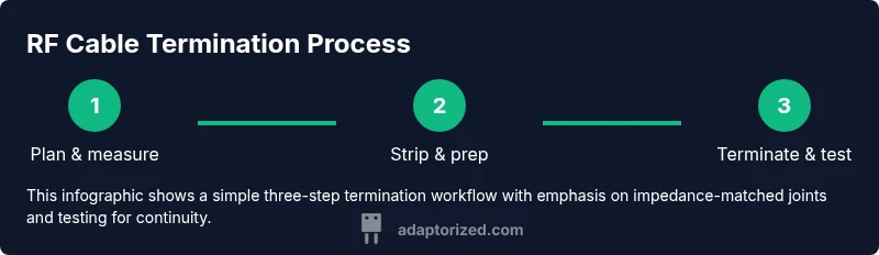
Plan route and measure length
Assess your setup and plan the cable route. Measure the distance between devices and add a little extra for routing bends. This prevents unnecessary joints and ensures a clean, repeatable run.
Tip: Record the final length before cutting to avoid rework. - 2
Prepare the connector end and strip cable
Use a coaxial stripper to remove the jacket and dielectric precisely as needed for the connector. Avoid nicking the center conductor or dielectric, which can create weak points.
Tip: Take your time; a small nick can propagate failure under load. - 3
Attach connector using correct method
Choose the appropriate termination method (crimp or solder) per your connector specs. Ensure a tight, uniform grip and correct alignment of the center conductor with the connector pin.
Tip: Do not twist the conductor during crimping; misalignment causes poor contact. - 4
Seal the joint and route the cable
Slide heat shrink over the termination and heat it evenly to seal against moisture. Route the cable with gentle bends and avoid sharp angles that cause impedance changes.
Tip: Use a gentle bend radius and secure the cable to prevent movement. - 5
Test continuity and basic integrity
Use a continuity tester to confirm a complete path from end to end. Visually inspect the jacket for any cuts or pinches that could affect shielding.
Tip: If continuity fails, re-check the connectors and ensure there is no short to shield. - 6
Perform a SWR/return-loss check
Connect the assembled cable to compatible test gear and perform a basic SWR check to verify reflections are within expected range for your frequency range.
Tip: Repeat with a different connector or shorter length to isolate issues. - 7
Label and document the run
Mark the cable with length, impedance, and connector type. Document routing and testing results for future maintenance or upgrades.
Tip: Well-documented cables save time on future projects.
Your Questions Answered
Why is impedance important in RF cables?
Impedance determines how efficiently signals travel along the cable and how much is reflected back at joints. Matching impedance across all components reduces reflections and improves overall performance.
Impedance matching reduces reflections and improves signal quality.
Can I use Ethernet cables for RF signals?
Ethernet cables are not designed for RF frequency performance and can introduce impedance mismatches and noise. Use RF-specific coax for reliable results.
Ethernet cables aren’t suitable for RF signal paths.
How long can RF cables be before performance degrades?
Length affects signal integrity, especially at higher frequencies. Plan runs to minimize length and avoid unnecessary extensions that add loss.
Longer cables can degrade signal quality, especially at high frequencies.
What’s the best way to terminate a coax cable?
Follow the connector’s recommended termination method (crimp or solder) and ensure impedance continuity. Use proper tools and cleaning steps for reliable joints.
Terminate with the method specified by the connector and test for continuity.
Is it safe to use cleaners on connectors?
Yes, but use electronics-grade contact cleaners and allow parts to dry fully before assembly to avoid residue that can cause poor contact.
Use proper contact cleaners and let parts dry before assembly.
What are common signs of a bad RF cable?
Frequent signal drops, unexpected noise, or poor continuity indicate possible damage, a loose connector, or shielding issues. Inspect and test to pinpoint the cause.
Look for signal drops or noise and test for continuity.
Watch Video
What to Remember
- Choose 50-ohm coax for most RF projects to minimize reflections.
- Maintain clean, matched terminations across all connectors.
- Keep runs short and routed away from EMI sources when possible.
- Test cables with continuity and SWR checks to verify integrity before use.