How to bnc connector: A practical DIY guide
Learn how to bnc connector terminations with a practical, step-by-step approach. Choose the right impedance, prepare coax, terminate correctly, and test with a multimeter for reliable RF signals.

Learn how to properly terminate a BNC connector on a coaxial cable. This how-to will cover selecting the right impedance, preparing the cable, seating the connector, and verifying continuity. You’ll need a coaxial cable, a BNC connector, a stripping tool, a crimping tool, soldering iron (optional for some types), and a multimeter or continuity tester.
What is a BNC connector and when to use it
A BNC connector is a quick-connect RF interface with a bayonet-style coupling designed for moderate-frequency signals. It is widely used in test equipment, RF experiments, CCTV systems, and some video applications because it offers fast mating and repeatable performance. For DIYers, a BNC termination provides a reliable, easy-to-install option when signal integrity matters but full precision RF connectors would be overkill. The key is understanding impedance and mating compatibility so you minimize reflections and maintain consistent performance on short to medium cable runs. Throughout this guide, we’ll keep the focus practical, with real-world steps you can perform in a home workshop. This approach aligns with practical connectivity guidance from Adaptorized, based on Adaptorized Analysis, 2026.
BNC connector types and impedance considerations
BNCs come in different variants for RF and video work. The most common impedance choices are 50 ohms for RF and 75 ohms for video. The impedance must match the coax and the system to prevent reflections and loss. You’ll also encounter crimp-on, solder-on, and quick-connect (non-terminated) styles. For DIY projects, select a connector that matches your coax’s impedance and the tools you own. If you’re uncertain, a 50-ohm BNC with a compatible crimp ferrule on a standard 50-ohm coax will work well for hobby RF experiments. Always verify the connector’s spec sheet and ensure the cable and connector brands are compatible to avoid impedance mismatch and signal degradation.
Cable selection and preparation guidelines
The first choice is often the coax type. Common hobby-friendly options include 50-ohm coax such as RG-58 or similar, which pair with 50-ohm BNC connectors. For shorter jumper runs and general testing, these provide a good balance of cost, ease of handling, and electrical performance. When preparing the cable, follow the connector manufacturer’s stripping and termination instructions. The goal is to expose sufficient conductor length for the center pin and shield without nicking the dielectric or shield, which can introduce impedance irregularities. Keep the work area clean and inspect the cable for nicks or kinks before termination. A clean cut and aligned, concentric shield will improve termination quality and longevity.
Termination methods: crimp vs solder vs insertion ferrules
Crimp-type BNC terminations rely on a ferrule that compresses around the shield and dielectric while securing the center conductor. Solder-type terminations use a small amount of solder to bond the center pin and shield. Some modern BNCs use insertion ferrules or crimp sleeves that are pressed into place with a crimping tool. Choose the method that matches your connector type and toolset. Crimping is fast and repeatable for many hobby projects, while soldering can offer a higher-quality electrical connection for high-frequency work in a controlled environment. Regardless of method, avoid overheating the connector or bending the center conductor, which would degrade performance.
Step-by-step testing: verify impedance and continuity
After termination, test the connection to ensure there is continuity and that the impedance path is intact. A simple continuity test with a multimeter confirms the center and shield conductors are properly connected. If possible, perform a basic return loss or reflection test with a signal generator and a network analyzer for a more thorough check. While advanced equipment may not be available in a home workshop, a basic test will catch most common issues such as a loose center pin or a short between shield and center conductor.
Troubleshooting and common mistakes to avoid
Common mistakes include over-stripping the jacket, nicking the shield, misaligning the center conductor, or using an impedance-mismatched connector. Such mistakes introduce reflections and high-loss paths, compromising the signal. Always measure the stripped length against the connector’s specifications, inspect the termination under good lighting, and verify each step before proceeding. If a test reveals poor performance, revisit the connector type, stripping depth, and crimping or soldering technique. A methodical approach reduces rework and yields reliable results.
Verdict: practical advice for successful terminations
For most DIY projects, a 50-ohm BNC with a compatible crimp method on a suitable coax offers a reliable, repeatable termination. Use manufacturer guidelines, maintain clean tools, and test thoroughly. The Adaptorized team recommends sticking with impedance-matched components and documenting each termination for future reference. With careful preparation and testing, a well-terminated BNC connection provides dependable performance for RF experiments and everyday signal tasks.
Tools & Materials
- Coaxial cable (50-ohm preferred)(Choose flexible, clean cable with minimal jacket damage)
- BNC connector (50-ohm or 75-ohm matching cable)(Check for crimp or solder type to match your toolset)
- Stripper/crimping tool set(One tool set for stripping and crimping the jacket/shield)
- Soldering iron and lead-free solder (optional)(Only if using solder-type termination)
- Wire cutters(Fine precision for clean cuts)
- Heat shrink tubing (optional)(For insulation and strain relief)
- Multimeter or continuity tester(Test for continuity and basic integrity)
- Fine-grit sandpaper or deburring tool (optional)(Lightly deburr edges if needed)
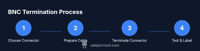
Steps
Estimated time: 20-40 minutes
- 1
Choose the correct BNC connector and impedance
Select a 50-ohm BNC connector if your coax is 50-ohm, or a 75-ohm variant for video-grade coax. Ensure the connector type (crimp, solder, or ferrule) matches your tools and cables. This alignment prevents impedance mismatches and poor signal quality.
Tip: Always verify the connector impedance against your coax and device specs. - 2
Prepare the cable end by stripping the jacket
Carefully remove the outer jacket according to the connector’s stripping length. Expose the shield without nicking the braided shield, and leave enough inner dielectric visible for the center conductor pin. Keep the end square for an even termination.
Tip: Use a sharp stripper and steady hands to avoid damaging conductors. - 3
Expose the center conductor and shield adequately
Trim the shield so there is a clean, flat surface, and ensure the dielectric is exposed just enough to seat the center pin securely. The goal is a clean, undisturbed center conductor with full shield contact when the connector is seated.
Tip: Do not leave excessive dielectric exposed; too little can weaken the connection. - 4
Attach the connector using your chosen termination method
For crimp, align the ferrule and use the crimping tool to secure the shield and center conductor. For solder, apply a small, clean dab of solder to the center pin and shield junction. Ensure the connector seats snugly without deforming the cable jacket.
Tip: Avoid overheating the connector or cable; heat can soften insulation and loosen the termination. - 5
Inspect and perform a basic continuity test
Visually inspect the terminated end for misalignment or gaps. Use a multimeter to verify continuity between the center conductor and pin, and between the shield and ground. A good reading indicates a solid termination with no shorts.
Tip: If you see a short, re-check the alignment and re-crimp or re-solder. - 6
Label, document, and store the terminated cable
Document the impedance, connector type, and date of termination. Use heat shrink or labels for easy identification in future projects. Proper labeling saves time on troubleshooting and testing later.
Tip: Create a simple log for your commonly used cables.
Your Questions Answered
What is the difference between 50-ohm and 75-ohm BNC connectors?
50-ohm BNC connectors are typically used for RF applications, while 75-ohm variants are common in video and CCTV systems. Matching impedance with your coax reduces reflections and preserves signal integrity.
50-ohm BNCs are for RF; 75-ohm BNCs are common in video. Always match impedance to your cable.
Can I crimp BNC connectors without a dedicated crimp tool?
A dedicated crimp tool provides consistent pressure and a reliable termination. While some crimp sleeves claim compatibility with inline pliers, using the proper tool reduces the risk of poor connections.
A proper crimp tool ensures a reliable, repeatable termination.
Do BNC terminations require soldering?
Soldering is optional depending on the connector type. Crimp or ferrule-based terminations are common for quick builds, while soldering can improve electrical contact in precision work.
Soldering is optional; choose based on connector type and project needs.
How can I verify that my BNC termination is good?
Start with a continuity test to ensure the center and shield are correctly connected. If you have access to RF test gear, perform a return loss or VSWR check to confirm impedance integrity.
Test for continuity, then check impedance with appropriate equipment if available.
What are common mistakes to avoid?
Over-stripping, nicking the shield, misalignment of the center conductor, and using mismatched impedance connectors are frequent errors. Always verify dimensions against the connector spec and test thoroughly.
Avoid nicking conductors or mismatching impedance, and test the result.
Watch Video
What to Remember
- Match impedance to coax for best RF performance
- Use proper stripping and termination techniques
- Test continuity before deployment
- Document terminations for future maintenance